消费性产品
- VGA 风扇 - 电竞灯控
- 电容式水位侦测
- MA35H0 HMI 點餐系統
-
NuMaker-Lighting-ARGB Development Kit

-
Magic Board
-
NuEzAI-M55M1 Development Platform
-
具有触控按键和语音提示功能的智能型 ITO 面板解决方案
- 智慧人机介面
- 世界首创内置 e-Marker 用于 USB4 设备的重定时器芯片
- HMI 平台与图像链接库介绍
- Gaming Lighting and Cooling Fans Control
- New HMI Platform NuMaker-HMI-MA35D1
- 宠物追踪装置
- Soy-milk Maker Driver
- CSP MOSFET
- TWS 耳机充电盒
- M031BT 双模电竞鼠标方案
- 四合一智能电子锁
- 耳机
- 婴儿用品
- 数码相机 / 摄像机
- 数字录像机
- 教育玩具
- 游戏机
- 家电
- 多媒体盒
- 微型打印机
- 安全监控面板
- 音频支付
- 烟雾 / 一氧化碳探测器
- 条形音箱
- 玩具
- 婴儿监护器
- 语音识别
- 加热型厨电
- 无线充电
- 半桥电磁炉
- 智能投影仪
- 激光电视
- 六爪机器人
- 智能插座
- USB汽车仿真驾驶系统
- 空中鼠标 (遥控器)
- 数字电话
- 平板手机 / 平板计算机
- 智能型手机
- 对讲机
工业应用
- Capacitive Water Level Detection
- 低功耗自动运作模式平台
- MA35D1 双系统(RTOS & Linux)应用展示
-
N9H31 HMI 人机平台
-
NuMicro® MA35D0 工业边缘装置
-
NuMicro® MA35H0 工业人机平台
- ARGB 风扇驱动方案
- 工业电子秤
- NuMicro® MA35D1 HDMI 影片播放
- NUC980 OpenWrt 图形化管理网关
-
DALI系统方案 – 控制设备与控制装置
-
DALI系统方案 – 应用控制器
-
空清机
- Out-of-band (OOB) Management Solution for Edge Devices
- 边缘运算范例之车牌辨识系统
- 通用串行总线端口管理控制器方案 USB Type-C PD 3.0 快充
-
RF-GaN PA Module for 5G Base Station
- 伺服电机控制方案
- 具多国语音播报 电梯内呼板
-
电容式触控型温控器
- LoRaWAN 生态系统
- 交互式人机界面解决方案
- 随插即换工业量测开发平台
- 物联网整合开发平台
- NB-IoT 物联网开发平台
- 工业远程控制装置 (RTU)
- 数字辨识水表
- 标签打印机
- 人脸识别考勤机
- 二维条形码扫描
- 智能卡片阅读机
- 电子秤
- 电动自行车
- 电表
- 人脸识别
- 风扇
- 指纹识别
- 燃气表
- 热量表
- 电子收银终端机
- QR码扫描器
- 水表
- 8x8x8 光立方
- 门禁控制系统
- 电梯解决方案
- LED 显示屏
Docking of iPhone / Android
-
 视频长度 - 21:57新唐 NuMicro M032 / M032 微控制器集成了工作频率高达 72 MHzArm Cortex-M0 内核,16〜512KB 闪存,2〜96KB SRAM 可以选择,封装从 20 到 128 PIN,还提供 QFN32 紧凑型封装 。 - 更多产品资讯,请至新唐科技网站 https://www.nuvoton.com/?utm_source=bb&utm_medium=video&utm_campaign=all 购买管道:https://tmall.nuvoton.com/
 -
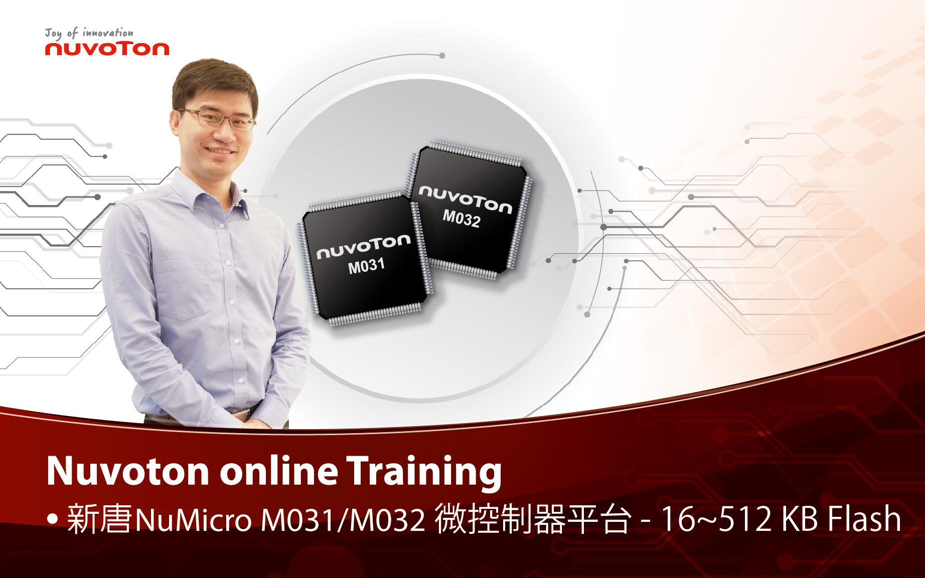
 创新产品 学习 视频长度 - 2:6新唐 NuMicro M031/M032 微控制器集成了工作频率高达 72 MHz Arm Cortex-M0 内核,16~512KB Flash、2~96KB SRAM 可供选择,封装从 20 到 128 PIN,压范围支援 1.8~3.6 V。 #Product #Learning #Basic #zh-Hans - 更多产品资讯,请至新唐科技网站 https://www.nuvoton.com/?utm_source=bb&utm_medium=video&utm_campaign=all 购买管道:https://tmall.nuvoton.com/
 粤公网安备 44030502010001号